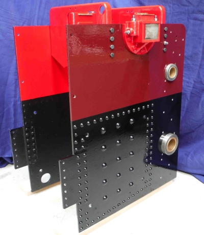
The horn plates will eventually bolt to the firebox end of the boiler and will support the tender.
On a full size traction engine, there would be dozens of rivets holding the horn plates to the boiler, with a small gap between. On this 1/3 size engine, this is not practical or necessary, so all the rivets you see are actually dummies. The horn plates will attach to the boiler using four large bolts with spacers.
The insides are painted with smokebox paint to protect against the heat, but the outside is engine enamel.
KITS 9-
1/3-
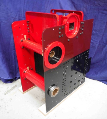
The lower tube is for the rear axle. Above this is the second shaft axle tube, which is for the gears that drive the rear wheels. At the top are the bearing supports for the crankshaft. The bearing blocks themselves are a future kit.
The shaft tubes are fitted with bronze bushes. These are fed with oil from the little brass oilers. These have tubes inside, and the oil is fed down using a wool wick. I had to buy the untreated (worsted) wool from a steam supplies company.
The bearing supports also have oilers on the top which work in similar way but have a higher capacity as the crankshaft runs faster.
The horn plates are held together by the spectacle plates. There are apertures for the connecting rods from the pistons to the crankshaft and for the valve gear rods.